DISCLAIMER:
Please note: This document & and the MobileForcesED are officially unsupported in ANYWAY by Realtime Worlds & Rage Plc so use at your own risk and make sure you backup any original MF files before you start tampering otherwise you might need to reinstall the game.
Post any comments or questions you may have in the official Mobile Forces community forums http://forums.mobileforces.org/ and we will try to help where possible.
Have fun with the editor, we look forward to seeing the results
Cheers
The Realtime Worlds Team
Si ‘XEON’ Donbavand [RAGE]
This document has been written by members of the Realtime Worlds – Mobile Forces team.
SECTION 1: THE MOBILE FORCES EDITOR
The following is a basic overview of ‘MobileForcesED’. This document is not a tutorial; it just explains how to implement the new features that the new editor contains.
Static Meshes.
Static meshes (SM) are used to create high poly objects within the Mobile Forces levels. Before you decide to convert any BSP to SM, first make sure that you have applied the correct textures and that they are scaled and lined up properly. It is not possible to scale or change texture co-ordinates on a SM.
How to convert BSP to staticmesh (SM).
- Select the BSP brush/brushes that you want converted to SM, then right click to bring up the actor toolbar. Select ‘Convert To>>Hardware Brush’
- Then enter the name you would like this SM to be known as in the ‘Name’ field. Leave both the ‘Package’ and ‘Group’ fields blank.
- You will then see that a green mesh resembling the original BSP has been created. The original BSP is still selected, you can now delete this if you like, my advice is to keep it and move it off to another space outside the level. Converting BSP to SM can sometimes take a few attempts to get everything right.
Sometimes you will find that your SM doesn’t seem to be affected by any lights. This is usually due to the placement of the pivot point of the SM.
How to make sure a SM will light properly.
- You must make sure that the SM’s pivot point is not inside the SM or any BSP or outside the level.
- The easiest way to ensure this doesn’t happen is to select a new pivot point. Select the ‘Wireframe Window’ then click on the ‘Show Large Vertices?’ icon (the one on the far right), this will give each vertice a large square that is much easier to click on (a little tip on selecting vertices, don’t actually click on top of the vertice, try clicking slightly to the side). Then set the grid setting to 1. Then simply select a vertice to be the new pivot point of the SM.
Sometimes the level of lighting on a SM doesn’t match the surrounding BSP, at times they can look too light/dark.
How to change the ambient level of a SM.
- First of all you must click in open space to make sure that nothing is selected. Then right click on the chosen SM, and select ‘StaticMeshActor Properties’ from the actor toolbar.
- Within the ‘StaticMeshActor Properties’ window, select ‘AmbientLight’ you will then have three fields. ‘AmbientBlue’, ‘AmbientGreen’, and ‘AmbientRed’, you may change these values to achieve the level of lighting that you are looking for.
Some SM’s look fine with each side having a sharp difference in shade to their connecting sides, but some SM’s would look better if the shading on the connecting sides were smoothed, like a cylinder for instance.
How to smooth a SM.
- Select the chosen SM. Then in the command line type ‘staticmesh smooth’ then press return.
- The SM will now be smoothed; you will have to re-calculate the lighting in the level to see the result.
- If you preferred the SM before you applied the smooth command, you can un-smooth the SM in the same way. Simply type ‘staticmesh unsmooth’ in the command line and press return.
How to merge multiple SM’s.
- Select all of the SM’s that you wish to merge. Then simply type ‘staticmesh merge’ in the command line and press return.
- There is no way to separate the SM after it has been merged, so you might want to keep a copy of the separated SM’s somewhere outside the level.
SM’s can be created and textured in 3DSmax, then imported into the level. I would highly recommend that as many SM’s as possible be created in this way.
How to import a SM from max.
- The object must first be saved as an .ASE in 3DSmax.
- Then click on the ‘Static Mesh Browser’ icon (it looks like a little archway). Then go to ‘File>>Import’. Then browse and select the .ASE file.
- The ‘Import Static Mesh’ window will appear. Then enter the name you would like this SM to be known as in the ‘Name’ field. Leave both the ‘Package’ and ‘Group’ fields blank.
- After the SM has been imported select ‘Edit>>Add To Level’, the SM will now be added to the level ready to be positioned properly.
Sometimes when a SM is imported from 3DSmax the scale is not quite right, this can be changed. Although the scale cannot be changed on one particular axis, it will affect all of the axis.
How to change the scale of a SM.
- First of all you must click in open space to make sure that nothing is selected. Then right click on the chosen SM, and select ‘StaticMeshActor Properties’ from the actor toolbar.
- Within the ‘StaticMeshActor Properties’ window, select ‘Display’. This adds a host of new fields.
- Find the field that reads ‘Drawscale’ then change the amount to change the scale of the SM.
- Note: you cannot change the pivot point of a SM while it has been scaled, if you need to change the pivot point of a SM simply change the scale back to 1.00 then change the pivot point then change the scale again.
New lighting.
There are two new types of light that have been added to MobileForcesEd.
Sunlight.
- This is a light source that can be pointed in any direction at any angle. This light hits everything in the zone it is placed.
SpecialSunlight.
- This light is exactly the same as the ‘Sunlight’ actor, although this light will affect every zone.
How to add a Sunlight.
- First click on the ‘Actor Class Browser’ icon (it looks like a little pawn chess piece). Then go to ‘Light>>Sunlight’.
- Then in any window, right click in open space. The actor toolbar will appear, select ‘Add Sunlight Here’. A little yellow ball with a directional arrow will be placed in the level.
- You can now set the angle/direction the sunlight will shine at by changing the angle of the directional arrow, click on the sunlight actor and hold ‘Control, and the ‘left mouse button’ you can now change the angle of the directional arrow by moving the mouse. You will have to do this in different windows to move the arrow on different axis.
- The brightness and colour of the sunlight can be changed in the same way as a normal light.
New Zones.
The basic ZoneInfo has changed slightly in Mobile Forces, there is now the ability to add fog to each zone.
How to add fog to add a ZoneInfo.
- First click on the ‘Actor Class Browser’ icon. Then go to ‘Info>>ZoneInfo’.
- Then in any window, right click in open space. The actor toolbar will appear, select ‘Add ZoneInfo Here’. The ‘ZoneInfo’ actor will be placed in the level.
- Select the ‘ZoneInfo’ actor then right click on it, select ‘ZoneInfo Properties’ from the actor toolbar.
- Within the ‘ZoneInfo Properties’ window, select ‘ZoneInfo’. This adds a host of new fields.
- Find the field that reads ‘bFogZone’ then set the field to ‘True’.
- Then find the field that reads ‘ZoneLight’, again this opens new fields. Find the fields that read ‘DistanceFogColor’, ‘DistanceFogStart’, and ‘DistanceFogEnd’.
- ‘DistanceFogColor’ you can change the colour of the fog in exactly the same way as you would a light.
- ‘DistanceFogStart’ this is the distance that the fog will become it’s thickest, basically a solid colour, where you can’t see any further.
- ‘DistanceFogEnd’ this is the distance where the fog will begin.
The water zone’s in both UT and Mobile Forces are exactly the same with the exception of fog.
How to add fog to add a RageWaterZone.
- First click on the ‘Actor Class Browser’ icon. Then go to ‘Info>>ZoneInfo>>RageWaterZone’.
- Then in any window, right click in open space. The actor toolbar will appear, select ‘Add RageWaterZone Here’. The ‘RageWaterZone’ actor will be placed in the level.
- The settings can be changed in exactly the same way as a normal UT waterzone.
- Fog can also be applied to the RageWaterZone, it is done in the same way as before.
Vehicles can also be set to float in the water; this is done by adding a PhysicalWaterInfo.
How to add a PhysicalWaterInfo.
- First click on the ‘Actor Class Browser’ icon. Then go to ‘Info>> PhysicalWaterInfo’.
- Then in any window, right click in open space. The actor toolbar will appear, select ‘Add PhysicalWaterInfo Here’. The ‘PhysicalWaterInfo’ actor will be placed in the level.
- You must now find out the ‘z co-ordinate’ of the sheet used for the surface of the water. Do this by selecting the BSP sheet, and then select one of the vertices.
- Then right click on the sheet, the actor toolbar will appear, select ‘Brush Properties’. Within the ‘Brush Properties’ window, select ‘Movement>>Location’ then take note of the value in the ‘z’ field.
- Next select the ‘PhysicalWaterInfo’ actor then right click on it; select ‘PhysicalWaterInfo Properties’ from the actor toolbar.
- Within the ‘PhysicalWaterInfo Properties’ window, select ‘PhysicalWaterInfo’. Then enter the previously noted ‘z’ value in the ‘Waterheight’ field.
LoadoutZone’s are used for the spawn points for the team based game types. They will allow any player within the zone to enter the loadout screen and choose weapons.
How to add a LoadoutZone.
- First click on the ‘Actor Class Browser’ icon. Then go to ‘Info>>ZoneInfo>>LoadoutZone’.
- Then in any window, right click in open space. The actor toolbar will appear, select ‘Add LoadoutZone Here’. The ‘LoadoutZone’ actor will be placed in the level.
- The ‘LoadoutZone’ will need to be set up in the same way as a normal ‘ZoneInfo’.
- You can also determine which weapons will be available from the ‘LoadoutZone’, Select the ‘LoadoutZone’ actor then right click on it, select ‘LoadoutZone Properties’ from the actor toolbar.
- Within the ‘LoadoutZone Properties’ window, select ‘LoadoutZone>>aWeaponsInStore’, you will see a list of weapon types. You may alter this list to what you want.
In order to stop enemy team members entering the opposition’s Loadout room, you must place a LoadoutBlocker.
How to add a LoadoutBlocker.
- First click on the ‘Actor Class Browser’ icon. Then go to ‘CollisionShape>>LoadoutBlocker’.
- Then in any window, right click in open space. The actor toolbar will appear, select ‘Add LoadoutBlocker Here’. The ‘LoadoutBlocker’ actor will be placed in the level.
- You might need to alter the collision radius to fit the door that you are trying to block, first select the ‘LoadoutBlocker’ actor then right click on it, select ‘LoadoutBlocker Properties’ from the actor toolbar.
- Then within the ‘LoadoutBlocker Properties’ window, select ‘Collision>>CollisionRadius’. Then enter the required value in the ‘CollisionRadius’ field.
StaticMeshes are not occluded by BSP, we use anti portals to occlude StaticMeshes. Anti portals are created by setting a texture flag called ‘Anti Portal’ on any BSP surface. Anti portals should be used on very basic BSP, I usually use solid BSP sheets.
How to add an AntiPortal.
- Add a BSP sheet in the position where you would like to insert an Anti portal, and then left click on one of the surfaces. Then right click on the surface to bring up the ‘Surface Properties’ window.
- Click on the ‘Flags’ tab, then check the following boxes, ‘Anti Portal, Unlit, Two Sided’.
SECTION 2: MOBILE FORCES – GAME SETUP AND MORE
Screenshots.
- Screenshots, as PCX files should be imported into the package MyLevel with no group, and be named Screenshot.
- The variable Screenshot in the Levelinfo section of the Level properties should be set to this texture.
- Do not attempt to save Mylevel as a texture package, simply save the level when the above steps are complete.
The Minimap
- The Minimap requires a MinimapInfo (Info->RepicaltionInfo->MinimapInfo) to be added to the level.
- The variable Minimap in the Levelinfo section of the Level properties should be set to the name of this variable, which can be found in the Object section of its properties (It’ll likely be MinimapInfo0).
- The x and y extents of the level in unreal units should be put into the mapTop, mapBottom, mapLeft and MapRight variables of the minimapinfo actor.
Texture(s) for the map (which will probably be alpha-masked .bmp files) should be imported into the level with a command of the form:
texture import name="texture name" file="file.bmp" package="Mylevel" mips=off flags=2
typed into the Log window, where texture name can be anything you want and file.bmp is the full path to the map image.
- These textures should be added into the maptextures array in the LevelInfoActor.
- A 256*256 texture represents 16384*16384 unreal units (ie 1 pixel== 64 unreal units). So a map of the maximum available size would require 16 256*256 textures in a grid of 4 by 4. The top left pixel of the top left map texture will be at the top left location specified in maptop and mapLeft. The number of textures wide your minimap will be should be put into NumTexturesHigh and likewise the number of textures wide should be put into NumTexturesHigh.
| maptextures[0]
| maptextures[2]
|
| maptextures[1]
| maptextures[3]
|
- The textures should be put into maptextures columns first, ie a 2x2 map will be arranged:
Vehicle Collision.
- A new flag “No Physics” has been added to the surface properties.
- When set, vehicles will not collide with this surface.
- Zone portals may block vehciles if this flag is not set.
- Older maps before this flag was added will have to make sure this flag is set for all their zone portals.
- This flag can be used to create invisible collision geometry for vehicles.
Vehicles In Water.
- Add an Actor.Info.PhysicalWaterInfo.
- Set the water height in world units.
- There can only be one global water level for vehicles per map.
Create a Loadout Room.
- Create a Zone. Add an Actor.Info.ZoneInfo.LoadoutZone actor in this zone.
- The weapons that are available from this loadout zone may be changed.
- Add a “Actor.CollisionShape.LoadoutBlocker” infront of any entrances to the loadout zone. Set the team variable (0= BlueTeam, 1= RedTeam). This will stop players from other teams entering another teams loadout areas.
Vehicle Generators.
- Add a “Actor.NavigationPoint.RoadPoint.VehicleGenerator.HumveeGenerator” actor.
- The rotation of this actor determines the rotation of the vehicles that will be generateed.
BombPlacer.
- Add a “Actor.NavigationPoint.BombPlacer” wherever you want a bot to be able to place a laser trip bomb.
- Try and make BombPlacers only accessable by up to 2 other navigation points. e.g. A single corridor wide enough for one bot only.
- Avoid wide open areas for bomb placers.
- Note: These were never fully finished and may not work properly.
Ladders.
- Ladders can only go absolutely up and down. Sloped ladders are not allowed.
- Add a “LadderClimber” actor. The volume of this actor acts as the limits of the ladder.
- Adjust the CollisionHeight and CollisionRadius of this actor to define the shape of the ladder (This actors collision cylinder is always shown for convenience).
- The LadderClimber collision cylinder should poke above the platform you want to be able to climb to, this is so that when you run at the ladder from the top you will be caught in the LadderClimbers volume.
- The LadderClimber should be rotated so that it FACES the wall you wish to be able to climb.
- An “Actor.NavigationPoint.Ladder” actor should be placed at the bottom and top of any LadderClimber objects. This is so the bots can use them.
- Make sure that when you generate bot paths that matching Actor.NavigationPoint.Ladder actors are joined by a purple line. If they are not then position them in the overhead view so that they line up better.
Road Point.
- Vehicles can only travel from “RoadPiont” to “RoadPoint”.
- Vehicles cannot use “PathNodes”.
- The speed at which a vehcile will approach the next “RoadNode” can be set under the “MaxSpeed” property. This value is a simple scale where 0=Stopped, 128=Half max speed and 255=Max speed.
Navigation Point.
- Extra properties have been added to allow a bot to get from a “RoadNode” (in a vehicle) to a “PathNode” (on foot).
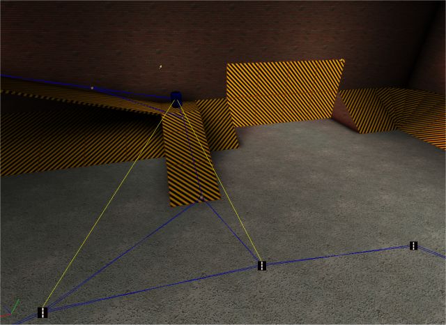
In this picture we see a RoadPoint network (at bottom of image). We also see a RageFlagBase (the blue barrel). The yellow lines represent where a bot would park his car if he was trying to get to the RageFlagBase. These carparks are calculated by working along the PathNodes until a RoadPoint is encountered. As you can see there are 2 RoadPoints encountered so 2 carpark links are created.
The distance that a carpark is searched for can be set in the “CarParkImportace” property which lives in NavigationPoint (RageFlagBase is a NavigationPoint). Its default is 255. This means that a maximum of 255 PathNodes will be traveresed until it finds a RoadPoint. If you find yellow carpark lines being created where you don’t want them then set CarParkImportance to cap how far away a carpark link will be created. Alternatively set “bAutoFillCarPark” to false in any RoadPoint that you do not want to be used as a carpark.
Creating a Road Network.
- The bots need a road network around the level to allow them to use the vehicles. Every “Game Object” should have a yellow car park line that leads to a road node. Every vehicle generator point should have a valid path to ALL of the game objects. All road nodes should be joined in one big road. There should be no small disconnected sub roads anywhere.
Ambush Points.
- Add these in areas you wan the bots to stand when in defense mode. Any team will use an ambush point.
- Use a “RageDefensePoint” for defining team specific defense positions. Make sure and set the “team” property.
- The “bDontUseInDomination” flag should be set if you want certain defense points to not be used in the holdout game type (the holdout game type used to be called domination). This is set to true by default for RageDefensePoints.
Multiple Gametypes in One Map
- The objects for multiple gametypes can now be put in one map, which should have the prefix ‘MF-‘ e.g. ‘mf-warehouse’.
- Most of the objects will be taken care of automatically, except for player start points and Weapons crates.
- Deathmatch–only player start points should be set to be for Team 255.
- Info->GameInfo->RageGameInfo->RDeathMatch->RageDeathMatch
- The CondGameType variable can also be set for any actor you wish to appear in only one game type, by setting it to the appropriate subclass of RageDeathMatch
Deathmatch.
- Add PlayerStart points liberally scattered around your map, in good tactical start places.
- Add “Actor,Decoration,Loadoutcrate_blue,LoadoutCrate_DM” actors (or one of its subclasses) beside the player start points, as necessary.
Captains.
- Add 2 "Actor.NavigationPoint.PlayerStart.CaptainStart" actors, one for each team.
- Set the team variable (0= BlueTeam, 1= RedTeam).
- Make sure and add a loadout crates for the captains as well.
CTF.
- Add 2 "Actor.NavigationPoint.RageFlagBase" actors, one for each team.
- Set the team variable (0= BlueTeam, 1= RedTeam).
SafeCracker.
- Add 2 "Actor.NavigationPoint.RageSafe" actors. One for each team.
- Set the team variable (0= BlueTeam, 1= RedTeam).
Holdout (used to be called domination).
- Add 1 "Actor.NavigationPoint.RageDominationTimer" actor.
Detonation.
- Add 2 "Actor.NavigationPoint.RageDetonationLock" actors. One for each team.
- Set the team variable (0= BlueTeam, 1= RedTeam).
- Also add any amount of "Actor.NavigationPoint.RageDetPossibleKeyPos" actors. These are the places that the "Key" object will appear in.
- At least one must be added.
Trailer.
- Add 1 “Actor.NavigationPoint.RoadPoint.VehicleGenerator.TrailerGenerator”. This will create a trailer+truck connected to each other.
- Add two “Actor.NavigationPoint.PathNode.RoadPoint.TrailerPark” actors. This is so the bots know where the delivery areas are.
- Set the team variable of the TrailerParks (0= BlueTeam, 1= RedTeam).
- Add an "Actor.CollisionShape.TrailerDelivery” at the same position (approximately) as each “TrailerPark”. These collision shapes are used to determine when the trailer has been delivered.
- Adjust the CollisionHeight and CollisionRadius of this actor to define the shape of the TrailerDelivery area (This actors collision cylinder is always shown for convenience).
- Set the team variable of the TrailerDelivery actors (0= BlueTeam, 1= RedTeam).
- Remember: Red team delivers to blue team zone. Blue team delivers to red team zone.
RageSprite In-Level Particle Effects.
Properties of each particle generator:
| Texture
| Sprite for particle
|
| SetLocation
| Set offset from base location
|
| RandomLocation
| Maximum random offset from base
|
| ConstVelocity
| Standard velocity of every particle
|
| RandomVelocity
| Maximum random velocity component
|
| Frequency
| How may particles to add per second
|
| Period
| How long to generate particles for
|
| Interval
| How long to not generate particles for
|
| PhaseShift
| How much this particle is out of sync with others
|
| Alpha
| How transparent to be
|
| Lifetime
| How long each particle lasts in seconds
|
| DrawSize
| How big each particle is
|
|
|
|
| DrawType
| What method to use to draw particle
|
| bAnimOnce
| Play sprte anim once
|
| bCollide
| Collide with stuff
|
| bGravity
| Subject to gravity
|
| bFadeAlpha
| Fade alpha over lifetime
|
| bFaceCamera
| Camera-facing particle
|
| Scale
|
|
| bRotate
| Rotate particle
|
| bDestroyOnCollide
|
|
| Rotationrate
| Rate at which particle rotates
|
To edit particles in-game:
- Go to windowed view of game
- Walk up to the particle effect you’re interested in
- Type: editactor class=RageEffects.ParticleEffect
- edit the properties in the dialog box that appears as you would in the editor
- Take a note of the values you have changed, and copy them into the particle effect’s properties in the editor.
Examples:
The FireyExample which can be found under ParticleEffect shows an example using five different particles – fire, two kinds of black smoke and two kinds of white smoke which occur at different locations (with a de
SECTION 3: MOBILE FORCES – THE HANDLING EDITOR
Creating a New Car
- Learn how to create and compile unreal script files in your own packages.
- Create a car model in max with separate parts for the body, left wheel, right wheel, axel and a separate low polygon collision model. Export these models as 3ds files. Convert these 3ds files to unreal model files using the unreal model converter “3ds2unr”.
- Create a script file for your vehicle eg. “TestCar.uc”.
- Write import commands for all of your new unreal model files. Use the “Humvee.uc” as a template for your own file.
- Fill out the default properties as explained in “Description of default properties” below.
- Create a “TestCar.col” file in the physics directory. You can create this file by editing it in notepad or by using the Mobile Forces collision exporter for 3dsmax4.
- Run the “handling editor” in the physics directory.
- Open the handling file from the physics directory. Its called “handling.hnd2”
- Select the automobile tab at the bottom. You should see a list of the games vehicles.
- Click the insert button on the right.
- You will be taken to the first page of the physics data for your new car. You must put in a name. This name MUST be the same as the name defined in the “Gen_Name” field of the default properties of your vehicle.
- Fill out the physics data for your vehicle as explained in “Description Of Physics Data” below.
- Save the handling data.
- Your vehicle is now ready to be used in a level.
- Vehicles can’t be placed in levels themselves. We need to use a VehcileGenerator to spawn your vehicle. Insert a VehicleGenerator in your level and set the “VehicleClass” in the vehicle generator to your new vehicle.
- You should now be able to play your level with your new vehicles
Description of default properties
These default properties are from Humvee.uc
defaultproperties
{
Meshes that the vehicle uses.
| DrawType=DT_DeviceMesh
| Leave this
|
| BodyMesh=humveeMesh
| Mesh to use for car body
|
| WheelMesh(0)=humwheelL
| Mesh to use for cars left wheels
|
| WheelMesh(1)=humwheelR
| Mesh to use for cars right wheels
|
| WheelBlownMesh(0)=HumveeWheelDL
| Mesh to use for cars left wheels when they are shot out
|
| WheelBlownMesh(1)=HumveeWheelDR
| Mesh to use for cars right wheels when they are shot out
|
| CollisionMesh=HumColMesh
| This is a simple mesh used for “Trace” collision detections
|
|
| (bullet shots,etc..).
|
| SuspensionMesh=BuggySuspension
| ONLY USED by the buggy RenderIterator(see below).
|
|
| Mesh used for suspension springs on buggy.
|
| AxelMesh(0)=Mesh'Rage.humaxel'
| Mesh used for the front and back axels
|
| NumDoors=3
| Number of entry points car has
|
| NumSeats=4
| Number of seats car has
|
| DriverSeat=1
| The number of the drivers seat
|
The aDoorsPos array holds the positions of all the doors.
The position is relative to the vehicle.
PositiveX is towards front of vehicle.
PositiveY is towards the left of the vehcile.
PositiveZ is towards the top of the vehcile.
aDoorsPos(0)=(x=10,y=66,z=25.5)
aDoorsPos(1)=(x=10,y=-66,z=25.5)
aDoorsPos(2)=(x=-133,y=0,z=25.5)
When a player leaves a vehicle they will be positioned at one of the door points. A valid place to put the player will be searched for from this point. The aDoorsExitDir array holds a normailsed vector. This is the direction the player is pushed away from the door when looking for a valid exit position. So (x=0,y=1,z=0) pushes the player to the left of the vehicle when looking for a valid exit position.
aDoorsExitDir(0)=(x=0,y=1,z=0)
aDoorsExitDir(1)=(x=0,y=-1,z=0)
aDoorsExitDir(2)=(x=-1,y=0,z=0)
The aSeats… arrays holds information on each seat in the vehicle. There should be one set of data for each seat.
| aSeatsSit(0)=1
| 0=Standing seat (ie back of humvee)
|
|
| 1=Sitting seat.
|
| aSeatsPos(0)=(x=15.5,y=32,z=55.55555)
| Relative position of seat in vehcile
|
| aSeatsRot(0)=(ROLL=0,PITCH=0,YAW=0)
| Relative rotation of seat in vehicle.
|
| aSeatsRotLimit(0)=(YAW=16384,PITCH=16384)
| Rotations/view limit of seat:
|
|
| Rot limit of 0 = No rotation limit
|
|
| Rot limit of 16384 = 90deg limit in both directions.
|
|
| Rot limit of 1 = Not allowed to rotate
|
| aSeatsDoor(0)=0
| Number of door to enter this seat from
|
| aSeatNearDrivers(0)=1
| If set to 1, a player entering this seat will be
|
|
| forced into the drivers seat instead, if it is empty.
|
| aSeatsBotDesire(0)=0.5
| How desireable seat is to a bot. (1=max)
|
| aSeatsProtection(0)=0.8
| How much protection from damage this seat
|
|
| offers 1=Invincible while in seat.
|
!!Very Important!! This name is used to look for
Gen_Name="HUMVEE"
Leave these at 1, they do not work properly.
DrawScale=1
BodyScale=1
WheelScale=1
Vehicle can have a petrol cap that if hit will blow up vehicle with one shot.
| PetrolCapPos=(x=-95,y=-55,z=35.5)
| Relative position of cap
|
| PetrolCapRadius=7
| Collision size of cap
|
Collision size of wheels. Used for shooting them out.
WheelRadius=20
Attachments to vehicle.
| bLight=true
| Set to true to enable “whos in vehicle” flag.
|
| LightPos=(x=116,y=0,z=100)
| Position of “whos in vehicle” flag.
|
| FlagPos=(x=-105,y=-38,z=95.5)
| Position of game pickup icon on vehicle (eg flag)
|
Engine sounds vehcile should use.
| EngineSound=Sound'HumveeSFX.Engine1'
| This should be a looping sound.
|
| EngineStartSound=Sound'HumveeSFX.EngineStart'
|
|
| EngineStopSound=Sound'HumveeSFX.EngineStop'
|
|
Minimum speed at which a vehicle can kill players by hitting them.
KillSpeed=8
Various camera parameters for each vehcile.
| FirstPersonPos=(x=90,y=0,z=65.5)
| Position of first person vehcile camera.
|
| NearCamera=250
| Distance of close in behind view camera.
|
| FarCamera=400
| Distance of far away behind view camera.
|
AI obstacle checking positions.
| FrontCheck=(x=110,y=0,z=40)
| Should be right in front of vehicle at wheel level.
|
| RearCheck=(x=-100,y=0,z=40)
| Should be right behind vehicle at wheel level.
|
| SideCheck=60
| Should be right at the side of vehcile at wheel level.
|
AI speed data. Not important. Use default data below.
| AI_TopSpeed=15.0
| Just the top speed of the vehicle
|
| AI_SpeedMultiplier=1.5
| Multiplier of speeds defined in RoadNodes.
|
The truck has six wheels, the buggy has 4. Must be 4 or 6.
NumberOfWheels=4
Vehicle can be slightly shiny. Set this for a shiny car.
| bMeshEnviroMap=true
|
|
| Texture=Texture'RageGfx.ReflectionTex0'
| Shiny texture to use
|
Must be number from 0 to 3. Choose best type for your new vehicle.
0 = Humvee, 1=Truck, 2=Buggy, 3=Armadillo.
This is used to remember the last camera mode you used for each vehcile type.
VehicleType=0
Force applied to vehcile when one of its wheels explodes.
WheelExplosionForce=15
Force used to up-right vehcile when its upside-down.
UpRightingForce=250
Special vehicle weapon given to player when driving vheicle. These VehcileWeapons are not real weapons but are used to determine who gets a kill when someone is run over. They are not proper game weapons.
VWeaponClass=class'HumveeWeapon'
How much of a pounding this vehcile can take.
Armour=0.68
Unused.
MenuName="stray Humvee"
The location of a vehicle is defined by its Centre Of Mass (COM). We must never place a vehicles location outside the level. This will never happen if the COM is placed inside the vehicles collisions spheres. However COM is not always inside a collision sphere. Use offset is used so shift the COM about until it is inside a sphere. Note: changing this value does not affect the handling of the vehicle OR move its actual centre of mass.
CMOffset=(X=0,Y=0,Z=32)
This defines the routines that are used to draw the vehicle. There are 2 types for cars.
“Rage.BuggyRI” is used for our buggy and it draws each wheel with independent susspensions. “Rage.CarRI” is the default one and draws the vehcile with linked axel suspension. If using the buggy RenderIterator then you will have to define a SuspensionMesh.
RenderIteratorClass=Class'Rage.BuggyRI'
}
Description of Physics Data
WARNING. WARNING. WARNING. WARNING. WARNING. WARNING. WARNING. WARNING.
Changing the physics files may:
Make your game incompatible with network games.
Stop the game from behaving as designed.
Ruin the single player game.
Always make a backup of your physics directory before you start tinkering.
WARNING. WARNING. WARNING. WARNING. WARNING. WARNING. WARNING. WARNING.
To edit physics data run the program “HandlingEditor.exe” in the physics directory.
Explanations of what each parameter does is explained in the Handling Editor.
To create handling data for your own vehcile it is best to copy one of the existing vehicles data, using the “Duplicate” button, and use this as the basis for your own vehciles data.
All vehicles physics data are held in one file, “Handling.hnd2”. This is a text file and can also be edited in notepad.
Each vehcile has a separate collision file , “VehicleName.col”. This is a text file and can also be edited in notepad.
It is possible to create several different types of handling data, MobileForces supports the following: Prop, Automobile and Trailer.
Several extra data sets are present in the editor but were never finished. These are: Boat, Hovercraft,Aeroplane and Helicopter. These are not supported in Mobile Forces.
However, if you want to have a go at creating some hovering craft, maybe even planes have a look at this
All the rigid body functions are visible in script:
native function ApplyForce ( Vector Pos, Vector Force );
native function vector GetTransVel ();
native function vector GetVelAtPoint ( Vector Pos );
native function vector GetPointWorld ( vector PointRel ); native function rotator GetChildRotWorld ( rotator LocalRot ); native function vector GetRotVel (); native function vector SetTransVel ( Vector Vel ); native function vector SetRotVel ( Vector Vel ); native function vector SetTransVelLocal ( Vector Vel ); native function vector SetRotVelLocal ( Vector Vel ); native function SetPlayerContolled ( bool In ); native function DebugMove ( Vector Vec ); native function float GetSpeed (); native function bool IsPhysicalCollision();
All you have to do is apply an upward force to make the car hover. The upward force could be scaled by the cars speed.
Back to the Future Hoverboards I hear ya calling ;)
SECTION 4: MOBILE FORCES – STATIC MESH TERRAIN
Software needed.
Photoshop or Paint Shop pro.
TerraEdit.
Mobile Forces Ed.
Step 1.
Create two folders within your TerraEdit folder called ‘terrain’ and ‘heightmaps’.
Step 2.
First of all you have to create a greyscale image make sure it’s 256 x 256 x 256 and save it as ‘terrain1.bmp’ into the ‘heightmaps’ folder. You can create this file using either Photoshop or Paint Shop pro.
Step 3.
Load up TerraEdit, then go to File\Import, open up the ‘heightmaps’ folder and select ‘terrain1.bmp’. You will then be asked to enter the grid scale and grid size. Enter 16 for the grid scale and 96 x 96 for the grid size. You will then be asked ‘It is not recommended that you create heightmaps larger than 32 x 32. Continue?’ Click on ‘Yes’.
Step 4.
You will now have a map loaded, you can move around using the same controls as Mobile Forces Ed. The next thing you will want to do is smooth off all of those harsh edges. Go to ‘Tools\Filter\Smooth’ you will see that the map instantly updates. Continue this process until you are happy with the shape of your terrain. When you are happy with the terrain go to ‘File\Export’ the save it as ‘terrain1.t3d’ in your terrain folder.
Note – maps can’t actually be saved in Terraedit (they normally crash upon loading), they can only be exported ready to be imported by Mobile Forces Ed. If for some reason you wanted to do anything extra to your terrain you would have to go back to Step 3, and begin smoothing the terrain again.
Step 5.
Load up Mobile Forces Ed. Select the builder brush (the red one), right click on the builder brush, select ‘Brush Properties’. Now within the ‘Brush Properties’ window select ‘+Brush\+MainScale\+Scale’. Now change the figures to X = 16, Y = 16, Z = 8. This will re-scale the builder brush to the correct size for a terrain to be imported.
Step 6.
Go to ‘Brush\Import’, then open up the ‘terrain’ folder and select ‘terrain.t3d’, (C:\..\TerraEdit\Terrain\terrain.t3d). You will then be faced with the ‘Import Brush’ window. Make Sure that only ‘Solid Mesh’ is selected, then click on ‘Ok’.
You will then have the terrain ready to add\texture\staticmesh.